Sunday, May 10, 2020

Hardwired Motion Detection for Insteon Home Automation System


Hardwired Motion Detection for Insteon Home Automation System

Why did I do this?
The wireless motion detectors for Insteon have worked well over the years, but changing batteries was a pain and the older style units were getting harder to find. The new units just seem so cheaply made and have a subpar mounting system.

The first thing I did was draw a schematic of how I could make this work:


I’ve often said “you can make anything work with a relay” J So once I had a design I went shopping for the parts to make this work.


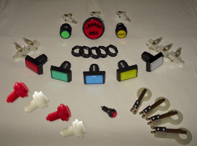
These 12V DC Motion detectors were China Made Plastic but had the features I wanted such as:

* Working rotation: 180°
* Voltage : DC 12V
* Loaded power: 10W-99W
* Detection distance: up to 12m (40 feet)
* Installation height: 1.5m-2.5m High (I have them between 6 and 8 feet)
* Induction lighting time: 5s-6min adjustable time (6 min is max but works for me)
* LUX setting: 2-2000lux adjustable
* Operating temp: -10~+40
* Operating humidity: <93%RH
* IP rating: Indoor application IP44 ( But should work outdoors very well, “Controls Face Down”)
* Material: ABS
* Size: (60 x 47 x 156)mm (approx.)
* Color: White

They are cheap, so I have 2 Spares just in case.

Found a nice 12V Power Supply on Amazon:


And it even has a backup battery! (Not included)


Now I need a relay. Only need 3 channels but put in a 4 channel (expansion?)


Some wire and a box to put it in:


And three 2450 I/O Links to communicate to the Insteon System:


First thing to do is test it on the bench:


Notice the plastic stand off’s I also found on Amazon to mount the relay in the box.

OK so it works; now to install it:
I will be installing three of these. One under my deck, one along the front of the house, and one along the back.


But first the motion detectors come with some weird thread size so I will need to adapt them to fit a standard weatherproof box. I did this using a ½” PVC pipe connector and reaming it out with my Dremmel so it fits over the flange on the detector. A little Super Glue and this will work!


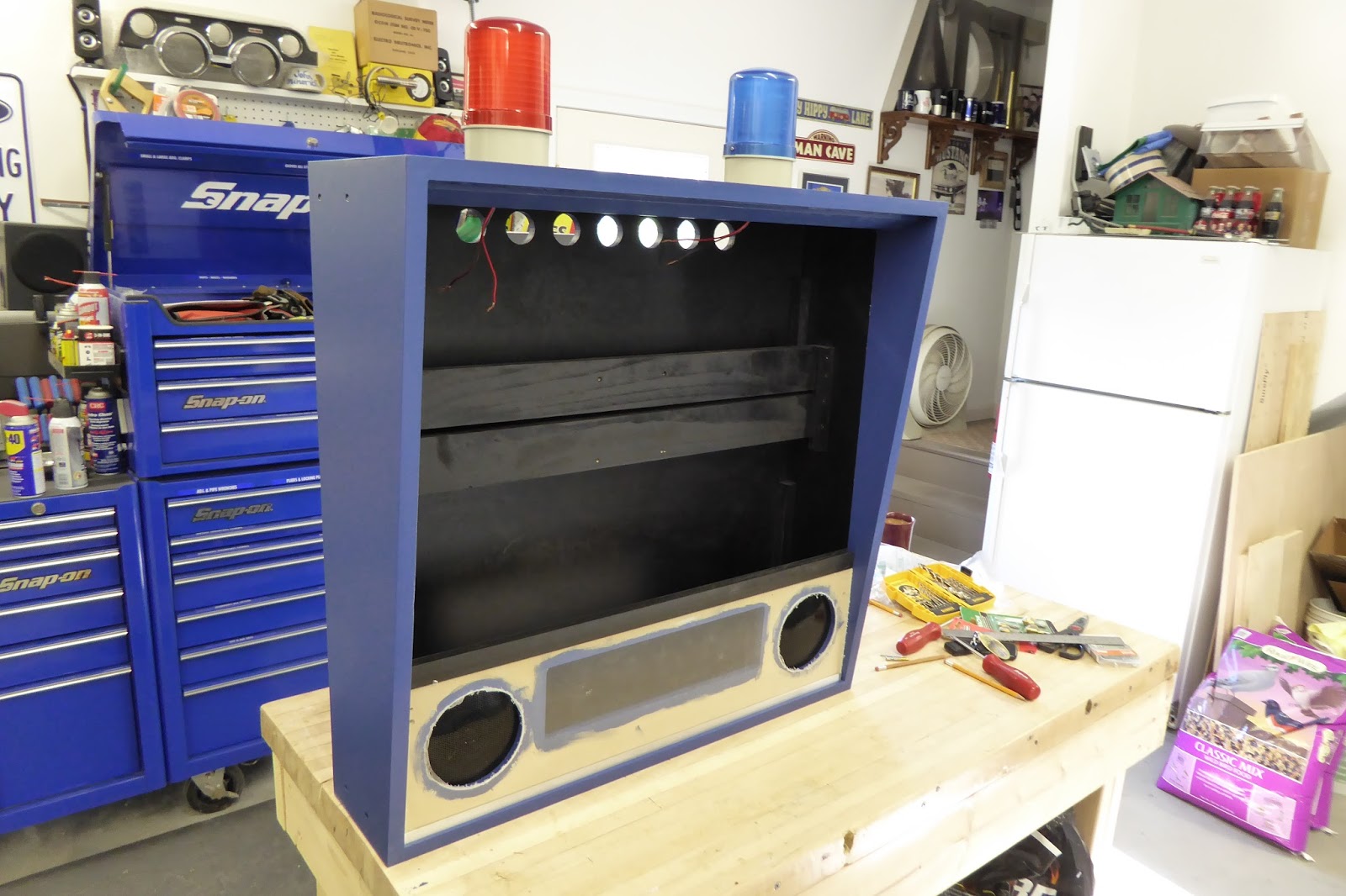
So now to install them:


1St one is under the back deck. It controls the flood light next to the door, and sends me a text and email if it is tripped.

This one is set to be on 24X7.


2nd one is in the front of the house. Notice the black tape on the face to narrow its field of view to run along the front of the house yet not pick up cars going down the street.


3rd one is behind the garage looking behind the house. It is programmed to trip both the house deck light as well as the back garage door light.


The controls are mounted in the basement next to the power panel:


My Insteon Home Automation System uses the ISY 994i to control things around the house.

The programming for the Back Motion and the Under Deck Motion


It took a few days to dial in the detectors both sensitivity and direction, but all seems to be working as planned. I did notice the sensors are more sensitive when it gets cold, this makes sense as they are Infra-Red detectors. I kind of split the difference so they are all around doing what is needed.


Wednesday, February 17, 2016

1967 Mustang GT Convertible - Rebuild and Replace worn out hinge


Rebuild and Replace worn out hinge.


The driver’s door lower hinge on my 67 Mustang is worn out. To the point that the door will no longer stay open. The metal bar that is supposed to glide on a roller has worn deep into the roller making it no longer function. In fact the bar has been worn to a sharp point and I am sure it is now cutting into the pin that holds the roller in place.  

Some repairs have a story, and rebuilding the hinges on my 67 Mustang is one of them.

First, my car is an early 67 so it has the cast iron hinges, not the stamped steel hinges Ford started using mid-year. They sell rebuild kits for the hinges, but after watching a You Tube video on what it takes to rebuild a hinge I was skeptical that this was something I could do in my garage. The guy in the video had to weld up a special tool to extract the pin the roller is on as it does not go all the way through the hinge so cannot be hammered out!


I found a set of hinges for sale on Ebay and placed a bid, thinking I would rebuild them and if I damaged them, no big deal the car still has a working hinge, although very worn out. I won the auction and was very pleased to find they were in very good shape, in fact the driver’s door was slightly worn but functional, and the passenger hinge was like new! So only the one driver’s door hinge needs to be rebuilt.


Getting the spring off was no big deal, I wrapped it with bailing wire and tightened it as much as I could with plyers and it came out. The pins came out easy using a punch and hammer, all except for the one pin with the roller that had no way to get behind it. I cut the roller off the pin being careful not to cut the pin, I then placed the pin in the vice and really cranked the vice down on the pin. I was then able to use my air hammer with the ball joint separator fork to drive the hinge up removing the pin. The photo on the left was staged to show an example using the passenger side hinge, but as I was writing this I noticed someone  has drilled a hole in it to allow the pin to be driven out. That’s an option to consider.

So the real problem for me was attempting to put the new pin with the roller back into the hinge. I found that in hammering the pin into the hinge the pin would expand or crush preventing the roller from turning. I destroyed two pins and rollers before I was able to get the pin in without damaging the ability for the roller to turn smoothly.  I accomplished this by slightly reaming the hole with a drill bit making the pin go in a little easier.

Tuesday, June 30, 2015

Virtual Pinball Machine Build

So I have decided to build a virtual pinball machine. I have spent days researching the project and even set up a test machine on my desktop PC to better understand how all the various programs and applications work together. I have decided to take the approach of building out a working but simple machine. Building the framework for being able to add more sophisticated components over time. New components available will make this much easier than it was just a few years ago.

The Computer that will drive the machine is basically a gaming PC with ample horsepower:


EVGA Z97 FTW (142-HR-E977-KR) LGA 1150 Intel Z97 HDMI SATA 6Gb/s USB 3.0 ATX Intel Motherboard.
Intel Core i7-4790K Devil’s Canyon Quad-Core 4.0GHz LGA 1150 BX80646I74790K Desktop Processor Intel HD Graphics 4600.
CORSAIR Dominator Platinum 16GB (4 x 4GB) 240-Pin DDR3 SDRAM DDR3 1866 (PC3 14900) Desktop Memory Model CMD16GX3M4A1866C9.
EVGA SuperNOVA NEX 750 G 80 PLUS GOLD Certified 750W Active PFC ATX12V v2.31/EPS 12V v2.91 SLI Ready CrossFire Ready Full Modular PSU 10 YearWarranty 120-G1-0750-XR NEW Haswell Ready Power Supply.
EVGA GeForce GTX 700 SuperClocked 02G-P4-2765-RX GeForce GTX 760 2GB 256-Bit GDDR5 PCI Express 3.0 SLI Support w/ EVGA ACX Cooler Video Card.
Crucial MX200 CT500MX200SSD1 2.5" 500GB SATA 6Gbps (SATA III) Micron 16nm MLC NAND Internal Solid State Drive (SSD).
All of the above will rest in a DIYPC Alpha-DB6 Black Acrylic ATX Bench Case Bench Computer Case for ATX/Micro ATX motherboard. This will provide easy access and allow all components excellent airflow in the pinball case.
A wireless Keyboard & Mouse will provide control and programming. I’ll build a space under the cabinet to store these when not in use.
The Back glass of the machine will have an AOC e2752She Glossy Black 27" 2ms Dual HDMI Widescreen LED Backlight Slim Monitor 300 cd/m2 20,000,000:1 (dynamic).

I may leave this in its case and build a flush mounting bracket with an apron around it.
The play surface will be a very inexpensive Changhong 42" Class 4K Ultra HD LED TV - UD42YC5500UA it has 4K Ultra HD Resolution (3840 x 2160) and a Narrow Bezel, Enhanced Motion Rate 240Hz,UC-Pro Engine, ECO-friendly, UHD Upscaling, Roku Ready, with 4 HDMI Inputs. For $275.00 I’m going to give this a shot!
I will remove it from its case and mount it face up as the pinball playfield. It will be 37.87" x 1.32" x 21.95". I’m a little worried about the 8ms response time, but for the price it is worth a shot! With the high quality graphics card pushing it, it may be OK.
Microsoft Windows 7 Professional 64 Bit SP1 Full Pro DVD & COA Keycode will be the operating system.

Now for some specialized Pinball parts I will use the following:


PinDMD V2
Play your favorite Visual Pinball tables on a REAL pinball DMD! Great for virtual pinball cabinets by saving that extra video card! Use the real thing!
Vishay DMD
The most common plug-n-play, complete module replacement for Williams/Bally (reference #5901-12784-00), Stern/Sega/Data East (reference #520-5052-00), Gottlieb, Alvin G and Capcom machines.

No soldering required and installation takes only minutes. This is the latest update of this display and offers state-of-the-art, crisp and clear graphics.

Features
Integrates with custom VPinMAME.dll
Runs 99% of Visual Pinball DMD tables.
Runs 99% of Visual Pinball alphanumeric tables using virtual alphanumeric DMD render code. (95% complete)
USB powered. No external power source needed. (PinDMD board only)
Plug and Play USB. (FTDI drivers *may* need to be installed)
Free 14-way DMD interface cable included.
USB Game Controller Device
No external drivers or programming needed. Automatically recognized by Windows and Linux systems.
Two axis motion sensor provides real-time x and y coordinates (joystick X and Y) for realistic nudging.

Automatically calibrates on each cold start!
New version with improved performance and reliability. Real-Time Game Interaction

Digital Plunger Support
Digital Plunger with Analog Input on the joystick Z-Axis ESD Protected Enhanced Inputs & Outputs
Supports 15 I/O connections (joystick buttons 1-15).
All inputs de-bounced. Software Support
Fully compatible with Visual Pinball, Future Pinball, PinballX, HyperPin, and more.


Lepai's LP-168AH 2.1 amplifier is the perfect computer partner. It provides up to 40 watts of power output to stereo speakers, in combination with a second dedicated subwoofer output capable of up to 68 watts of amplifier output. Bass, treble, and volume controls on the front of the amplifier let you adjust your music for the best possible sound from your speakers. The discrete subwoofer output is controlled separately from the stereo output.
Some assembly required! A precision CNC-cut American Maple plywood cabinet, accurate to 3/1000th of an inch, is packed flat and shipped. Easy to assemble and finished by the aspiring virtual pinball cabinet builder. (That’s Me!)

This is, by far, the most complete build your own pinball kit on the market today!

This kit is everything you need to build a base pinball cabinet, with all holes drilled and cut and corner blocks and braces included! Comes with complete step-by-step instructions on how to assemble.

Our Widebody inside dimensions are 23.25" x 45" playfield area, 52" overall length. A perfect fit for our Ultimate Cabinet Kit (Widebody) offering.
WPC-style backbox, flatpacked to be easily assembled. CNC-cut 3/4" American Maple with hinged 1/2" back panel for ease of access to mount and maintain your backbox monitor. Perfect for your virtual pinball project.


An unfinished WPC speaker panel is precision CNC-cut 3/8" MDF, just like back in the day! A perfect fit for 2 5.25" speakers.

This will also host the DMD display.
A complete set of buttons. The leaf switches were specially designed to ensure a solid connection when depressed at low current to ensure no fluttering or missing.

2 Red 1-3/8” shaft Flipper Buttons
2 White 1-3/8” shaft Flipper Buttons
4 VirtuaPin Leaf Switches
4 Nylon Pal nuts
1 WMS/Bally Launch Ball Button
1 WMS/Bally Start Button
1 Coin In Green Button
1 Red Momentary Button
5 Rectangular Buttons w/Lamp Assembly
Standard OEM (original equipment manufacturer) two-slot replacement coin door for Williams/Bally pinball machines.

Includes all the parts you need to replace the entire door - frame, operator/test buttons, lock and keys, slam tilt switch, lamp sockets and lamps, coin mech mounting brackets, coin switches, and wiring harness.

Fits all WPC and WPC-95 machines.

Does NOT include coin mechs.
Hardware Kit includes:
Standard Williams/Bally steel pinball legs.
Legs are 28.5 inches in height.
Chrome finish.
Plus all necessary hardware and Lockdown bar, leg brackets, door hardware, etc. Everything except the glass I will buy locally!

 
TARGUS ASF27W9USZ Privacy 27" 16:9 Wide Screen Filter LCD Monitor cps27. This is 100$ so have not ordered it yet, but may need one if the glare on the play surface from the back glass monitor is annoying during play. 
To Protect the investment I am adding a Tripp Lite IB8RM 8-Outlet Isobar Premium Surge Protector (2350 Joules). The remote power switch will mount under the machine near the front as the main on/off switch.


The system is going to be made up of quite a few software programs that should interact together to give the user a real pinball gaming experience. In fact many of the pinball games available use the original sounds from the ROM chips that were installed in those machines. Some of the software I will use in this build:
·         Windows 7 Professional SP1
·         Windows .NET Framework installed
·         PinballX. A Digital Pinball Front End
o   A menu system to select various pinball games
o   Works with mutable Pinball emulators
·         Visual Pinball 8
·         Visual Pinball 9
·         Future Pinball
·         VPinMAME - Cabinet Build 2.5.0
o   Custom build of Visual PinMAME - designed for multiple display cabinets, removes 'most' notices about improper sound emulation, option to disable crc checks, fastframes, etc.
o   Reported version number is 3.00 to avoid popups saying you need x.xx vpm to play. DLL is built on official released current source code revision 2.50
·         In addition there are many front end and add on programs to support many functions

I’m going to have the machine boot directly into the PinballX program and hide the operating system as much as possible. There are hundreds of tables available that will run on this system. I’m going to try and get between 25 and 50 games installed and tweaked in the next few months. From what I have experienced setting this up on my desktop PC, each game requires adjustments in the settings, and edits to the script files to make them run properly on the specific hardware being used. So this takes some time, but I enjoy it!

While there are a few who are attempting to capitalize on this technology, most of it is open source provided by those with a love for pinball machines and work tirelessly to recreate original games as closely as possible and make them available for free. There is also still some open copyright issues with many of the games as they do (for the most part) use the original Williams/Bally ROM data. Also the graphics and content such as Star Trek, The Simpsons, Tron, etc were originally licensed to the pinball machine builder, not for the software reproduction versions. That may be why these machines are not being sold built-out, and the ones that are have no games in them. It won’t be long before someone signs an agreement with the games original copyright holders and starts selling these systems retail. However they are still fairly complicated and would require a good PC/Electronics tech to repair them, unless the whole thing could be simplified into an appliance of some type.
   
At a high level, this is nothing more than a PC with three monitors. 1- The playfield 42” HDTV, 2- The Backglass 27” 16:1 monitor, and 3- The Dot Matrix Display (DMD). A sound system with a Sub-woofer, and pinball switches and plungers to interact with the PC. The game controller card even allows for nudging the machine, but be careful because it will tilt!

I still have many decisions to make… What color do I want to paint the case? Do I want to apply graphics to it? How to trim out the frames around the playfield and back glass, where to position the PC and other hardware in the case. What other add-ons might I want like strobes, flashers, LED’s, clickers, etc. I need to engineer a way to easily lift the playfield monitor and prop it up to get to the PC and wiring underneath it. I’ll need to keep the wiring neat and organized for easy repair if ever needed.

I have built many computers over the years, but this build has me especially excited. I can’t wait to get going so I can have it finished by fall. I will document the process and update the blog as I go along.
-------------------------------------------------------------------------------- 
June 30, 2015 - The first three parts arrive!


The 4K HDTV and the 27" Monitor arrived in just 36 hours - Thanks NewEgg!
Kind of looks like a pinball machine already?? :)


And later in the day the Bench Case arrived. I think it will fit nicely into the pinball cabinet.

So the project started with the PC build set up and test on a table top.


Each Game added to the system was documented for function early on in the build.


Early on there were some failures, such as a DMD that popped, and an LEDWiz that kept failing to be recognized by the computer?


After weeks of back and forth with the parts suppliers I had what I felt was a stable machine ready to be installed into a cabinet, but first I had to build the cabinet!


So out to the garage and start the second part of the project, the Pinball Cabinet build.


Looks like we are going to need some glue and the nail gun.  


Maybe some paint – White Inside, Blue Outside.


All during the assembly I was constantly asking myself where things would fit! Like a chess game thinking ahead three or four moves. This paid off as things progressed and the pieces started coming together.
Airflow, wiring, power, sound, lights, computer, TV and Monitors.


It was rewarding to see things starting to come together. I actually started to think “Hey, this might work!” 


  And then I looked at the bench and saw all those parts, still needing a home inside this box!

I cut a access door in the back to get to the PC. And for limited service, added a third fan, and started placing the various components to see what might make the best fit.


I reworked the coin door to allow the coin jam push button to trigger the micro switch for simulating inserting a coin.

Next step is to apply some graphics I created on my computer and had printed for the cabinet. The graphics represent various pinball games and the Multi-Ball indicates it can play Multi pinball games.


I did not create the graphics from scratch, I used a template someone had already created, and just modified it to add color and adjusted them to fit my needs. There is a great community of folks that allow guys like me to build something like this.

OK, time to fit the computer into the cabinet and start wiring things up.


Now time to take apart the 4K HD TV and build a frame so it fits into the cabinet.


Now to clean up some of the wiring and we are good to go!


In all it took over five months, and about $3K to build this. I am very pleased with how it turned out.


UPDATE: October 29, 2015 - Notice the glare on the play surface from the backglass lighting. Well I found a way to keep the effect, but eliminate the glare. I relocated the LED strips to behind the backglass monitor, and used reflective tape on the back of the backglass access panel so now the light is indirect, still looks good but no glare!